Angelo Pesce (@kenpex) recently tweeted:
This is a calibration poll. Please don't spoil the answer, RT appreciated - Do you know how a GPU knows which mips to fetch when a regular tex2D(tex,uv) is called with trilinear filtering?
— c0de517e/AngeloPesce (@kenpex) December 3, 2019
I would have counted myself as ‘not sure’, but I had a pretty good idea what it would involve and I was also pretty sure I could figure it out. Instead of just being pretty sure about it I decided to test my intuitions against a GPU and made this shadertoy.
Most of the code is machinery to get a triangle up that we can rotate around in 3D space. I find it vaguely amusing to write a triangle rasteriser in a fragment shader, so that’s what I did. This post is just about LOD, so if you’re interested in how the rasteriser works I recommend starting with Fabien Giesen’s The Barycentric Conspiracy.
So, mipmaps: we have a texture with a series of successively smaller mip levels, each filtered properly prior to rendering to avoid aliasing. In this post I’m just going to assume textures are always square, and always a power of two in size. These restrictions can be lifted but I don’t really see why you would, except maybe to save space when using very large non-square textures.
2D
I’d already done this in 2D for a small project of mine, so this coloured my intuition a bit.
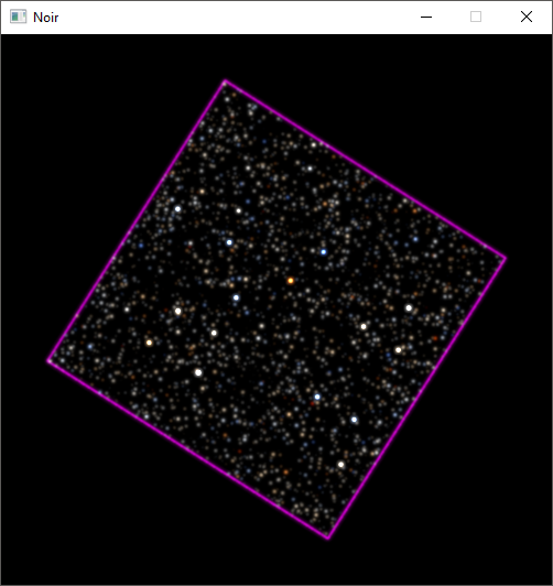
I was just drawing textures in squares of different orientations and sizes–it turns out an easy way to draw stars is to put a single very bright pixel in a big texture, and let mipmaps take care of the rest. So, here, we just have to do log2(texture_size / max(target_width, target_height)), that is, the of the inverse of the amount of scaling applied to the texture. To see why, each mip has relative sizes 1/1, 1/2, 1/4, ..., 1/n. We can get the relative size of the target rect by looking at its width and height, and we want to turn that relative size into an index into this list of sizes for which we have mips. So, we need the function . That’s .
Using also takes care of the fractional part of mip selection, so we can do trilinear filtering. If you think about it this is somewhat interesting, because we’re blending in a larger mip onto a target we already know is too small to not alias (in general). But having a jump discontuinity between mips looks way worse than low levels of aliasing.
3D
The main thing about 3D is that the LOD level can change across the surface of a triangle.
We need to think a bit more carefully about what’s happening. As we step along pixels in screen space, we also step along texels in texture space. While the former is constant, the latter steps vary in size due to perspective. Reasoning this way works in 2D, too, we just never had to: the constant, screen space step is our 1 in the series of relative mip sizes, and the relative, texture space step size is the denominator up to n. The question is how to get the step size at a given pixel, given that we shade each pixel independently of its neighbours. Now, I guess if you know the graphics pipeline quite well the answer to this jumps out at you, but I want to be able to justify why you would use the functions you do.
So, in 2D, the texture space step size is constant, and we’re able to compute it by assuming we’re going to draw the entire texture and comparing its original size with its new width and height in screen space. Now, to get the step size at a point in 3D, we can approximate it by asking about a smaller part of the texture, say a 2x2 patch rather than the entire thing, at that point. To drive the point home here, in 2D we had
with being some transform and being one side of the texture, and we’re replacing it with
and making really small. So, we need two of these for the derivatives in and , and you can get an approximation of them–basically this same one here–in OpenGL with dFdx() and dFdy().
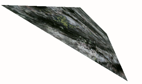
In the shadertoy, this is all implemented like this.
// uv comes in as an interpolated input
vec2 size = vec2(textureSize(iChannel0, 0));

vec2 dx = dFdx(uv * size);
vec2 dy = dFdy(uv * size);

float d = max(length(dx), length(dy));
float lod = max(0., log2(d));
vec3 col = textureLod(tex, p, lod).xyz;
Eyeballing the results this seems to work, but if we take the difference between textureLod() with our lod value versus using texture() and scale it up a bit to magnify errors, we get this.
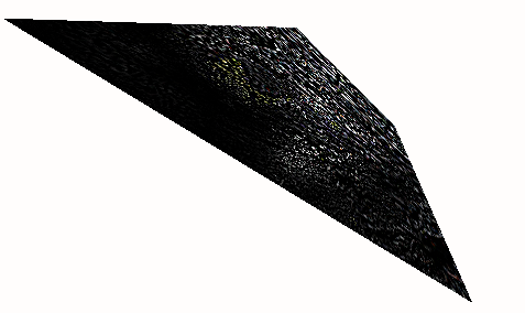
It should be black. The problem is obvious in retrospect, but rather than thinking too hard about it I had a look through the DX11 Functional Specification, which tells you to do this to the derivative vectors:
float A = dx.y * dx.y + dy.y * dy.y;
float B = -2.0 * (dx.x * dx.y + dy.x * dy.y);
float C = dx.x * dx.x + dy.x * dy.x;
float F = dx.x * dy.y - dy.x * dx.y;
F = F*F;

float p = A - C;
float q = A + C;
float t = sqrt(p*p + B*B);

dx.x = sqrt(F * (t+p) / (t * (q+t)));
dx.y = sqrt(F * (t-p) / (t * (q+t))) * sign(B);
dy.x = sqrt(F * (t-p) / (t * (q-t))) * -sign(B);
dy.y = sqrt(F * (t+p) / (t * (q-t)));
Ellipses
The source it references only as [Heckbert 89] turns out to be a master’s thesis, Fundamentals of Texture Mapping and Image Warping, which includes this in its appendices. The DX11 spec says it gives you a “proper orthogonal Jacobian matrix”, where proper is not a technical term. So, this is looking at the projection as a 2D transform from a point in screen space to a point in texture space. Now, it’s not linear, so you can’t represent it with a 2x2 matrix, but you can look at its derivative to get a linear approximation at a point. That’s the Jacobian, and we can construct it by just putting our derivative vectors in the columns of a matrix. But this Jacobian won’t be proper.
Basically, the issue is that up until now I’ve been neglecting to consider off-axis scaling. To solve this, we want to look at how the unit circle is transformed, not just the axes. That is, we look at the ellipse formed by applying the Jacobian to the unit circle. Weirdly, a pretty good explanation of this idea can be found in the Wikipedia article on singular value decomposition. Anyway, here’s a shadertoy showing how the above code modifies the axes:
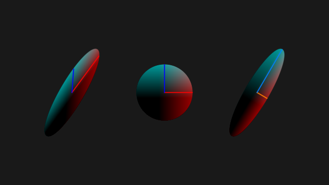
The right ellipse’s axes have been obtained by orthogonalising those on the left. The important thing is that both pairs of axes describe the same ellipse. The reason I went through the effort of creating that shadertoy, though, is because I wanted to check that putting those axes into the columns of two matrices would actually give you matrices that created the same ellipse. Because it’s a completely different transform, right, one of them isn’t even orthogonal! Of course, it does give you the same ellipse, and I guess the reason why that’s possible is obvious: each point on the plane is sent to a different place in either matrix, but the unit circle traces out the same ellipse for both. To that end, I’ve coloured each point by its original position inside the unit circle.
What this gives you is the maximum scaling in all directions, not just the directions the texture’s and axes have been mapped to in screen space.
Now, applying that correction, we’re much closer:
Still not perfect, though. I’m not sure what’s missing. DX11 allows for approximations here, and OpenGL’s specification doesn’t really say anything at all about it, so maybe that’s it. I’m really not sure.
Blocks
Finally, when I first wrote the rasteriser I did it the natural way, something like
if (inside_triangle) {
    color = calculate_color()
    write_pixel(color)
}
But if you look at the shadertoy now, you’ll see it’s written as
color = calculate_color()
if (inside_triangle) {
    write_pixel(color)
}
which looks like it wastes a bunch of effort colouring pixels it never writes. The reason for this is that the dFdx and dFdy functions aren’t magic: they really do take an approximation of the derivative by subtracting neighbouring pixel values from each other in 2x2 blocks. Since we’re running the shader in parallel for each pixel in the block, different pixels in the block can branch in different directions. At that point, the GPU is missing neighbouring values for dFdx/dFdy to compute derivatives with. The derivative computation breaks down and we can’t sample mipmaps at all. On my machine, this gave a LOD value of 0 which resulted in a seam of aliasing down the edges of triangles. At first I thought this was a bug in the inclusion test, but no, it’s just old fashioned non-uniform flow control.
End
I’m kinda disappointed I wasn’t able to get the LOD computation exact even after going through DX11 and OpenGL specifications. And it is just the LOD that’s wrong–with fixed LOD, the rasteriser does trilinear filtering down to texelFetch() just fine. Also, I’ve not talked about anisotropic filtering at all, which I’ve now discovered I know even less about than I thought I did. I’d like to know more about how it’s implemented on GPUs but it appears to be like, a trade secret, or something.
I think writing this post took longer than writing the shadertoy.